--->Diese Seite gibts auch in
Deutsch.
Optimal settings for TFT Displays
The best settings for CRT monitors are well-known, but who knows which settings are better for use with TFT displays? The following issues apply to both desktop displays and the ones built in into laptops as well as some beamers because the basic issues are the same.
Ideal, less ideal and unsuitable resolutions on TFTs
In contrast to CRTs, which spread each pixel onto a more or less amount of colour triplets on the screen, with relatively decreasing image quality at higher resolutions, TFTs show their best image quality at the highest resolution possible, at which each pixel exactly matches one triplet. In order to display lower resolutions, there are 2 possibilities:
- Using only a part of the screen, still matching each pixel to one triplet
- Recalculating the image so that it fits the whole screen
The first one gives the same image quality than on the highest possible resolution at the cost that a more or less huge amount of the screen is not used, showing a more or less wide border around the image.
In the second case the pixels have to be spread among the triplets so that the complete display is covered. The resulting gaps due to this method have to be filled by either matching some pixels to more triplets than others or by filling empty triplets with the average colour of the surrounding triplets (this is called (linear) interpolation).
The image quality is directly determined by the relation formed by the current resolution and the maximum resolution possible. If the result is a number without a fractional part each pixel is mapped to the same number of triplets. This case is the best. Fractional relations provide less image quality: A relation of 1.5 causes the pixels to map to one or two triplets alternatingly, a 1.3 relation causes every third pixel to map two pixels instead of one.
The following chart shows this using several common resolutions on 3 different displays resolutions. Best relations are marked green, usable are marked yellow, ugly looking ones are marked red. When 2 numbers are shown, the height and with have different relations.
| Resolution |
800x600 |
1024x768 |
1280x1024 |
1600x1200 |
| 1600 x 1200 |
- |
- |
- |
1.0 |
| 1280 x 1024 |
- |
- |
1.0 |
1.3 / 1.2 |
| 1152 x 864 |
- |
- |
1.1 / 1.2 |
1.4 |
| 1024 x 768 |
- |
1.0 |
1.2 / 1.3 |
1.6 |
| 800 x 600 |
1.0 |
1.3 |
1.6 / 1.7 |
2.0 |
| 640 x 480 |
1.3 |
1.6 |
2.0 / 2.1 |
2.5 |
| 512 x 384 |
1.6 |
2.0 |
2.5 / 2.7 |
3.1 |
| 400 x 300 |
2.0 |
2.6 |
3.2 / 3.4 |
4.0 |
| 320 x 240 |
2.5 |
3.2 |
4.0 / 5.3 |
5.0 |
| 320 x 200 |
2.5 / 3.0 |
3.2 / 3.8 |
4.0 / 5.1 |
5.0 / 6.0 |
Using a display with 1280*1024 standard resolution, the 640*512 mode would be a bit better than the 640*480 mode. Although all common graphic chips allow setting the resolution in 1, 2 or 4 pixel steps, only very few drivers support this. Sometimes it is possible to set it up in the registry, but that varies from driver to driver and version to version.
The image quality at different resolutions:
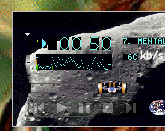
At the default resolution each pixel maps to one triplet, the relation is 1 : 1
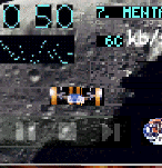
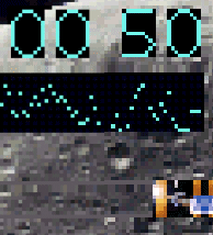
A relation of 1.3 : 1 causes a lot of distortion.
The left part of the image is with interpolation, the right without.
Both variants cannot provide a satisfying quality.
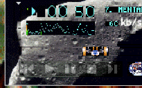
Using a relation of 1.6 : 1 the results are not better.
Take a look at the effect of the interpolation on numbers, letters and thin lines.
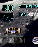
A non-fractional resolution of 2 : 1 provides an optimal image quality again.
Compared to a CRT, the pixels are even displayed sharper.
Further increasing relations (here 3.4 : 1) are lesser sensible to fractional relations.
The difference between interpolated mapping and simple mapping weakens as well.
As a result, it is recommended either not to use resolutions above half the default resolution or, if possible, not displaying them not in fullscreen. Resolutions below half the default resolution provide a usable quality. But only non-fractional relations can be recommended.
The refresh rate to choose
On a CRT, the best rate to choose is the highest one the graphic card and the CRT can handle properly in order to reduce flickering. But on a TFT display the triplets do not loose their brightness between refreshes and thus every refresh rate provides the same flicker-free result. But it is recommended for using low refresh rates on TFTs for two reasons:
- The graphic memory is less used
- On analog driven TFTs the image quality is often better.
The first reason is especially interesting for users of 3D hardware acceleration. Today, the 32-Bit-colour modes are most used since they are the fastest when displaying the graphic-based screens today (16 Bit is not faster when images are displayed since the colour conversion costs a lot of CPU time. Using 24 Bit, the unaligned data prevents fast memory accesses). Using a refresh rate of 85 Hz at 1280x1024 there are 420 megabytes of data per second which have to be read out of graphic memory just for displaying the screen. At 1024x768 there are still 250 megabytes to be transferred. Even on fast graphic cards a remarkable amount of memory bandwidth is already occupied by it.
By reducing the refresh rate by 1/3 down to 60 Hz the memory bandwidth needed is also reduced by 1/3, causing it to be available to other graphic chip functions. Especially users of onboard graphic chips without separate graphic memory and 3D gamers will be happy of the additional speed gained.
The second reasons only apply to displays with an analogue input. These are as sensitive to the quality of the video signal in the same way as analogue-driven CRTs when displaying the graphic. Using common resolutions like 1024x768 and 1280x1024 signal quality loss caused by the cable, graphic card converters working on their limit and the impact the heavy distortions on the internal power supply may have, can affect the image quality a lot. At 1280x1024 and 85 Hz about 125 MHz dot clock frequency is required, at 1024x768 there are still 65 MHz to produce and send via at least 2 connectors and about 1m of cable to the monitor. The frequency bandwidth required for proper display is 2 - 3 times higher. Reducing the refresh rate directly reduces the frequency bandwidth required, which, depending on the graphic card, the cable and the display can have a remarkable effect on image quality (especially text). Of course, in order to benefit from the effect the display has to be adjusted properly afterwards.
On a display with digital input this does not apply since the signal quality is not critical there.
Adjusting displays with an analogue VGA input
The analogue VGA signal contains three color components (RGB) and two signals for line (HSync) and refresh (VSync) signals. Their timing depends on the resolution, the refresh rate and the polarity of the synchronisation signals. However, the display can only detect the beginning of the lines properly, everything else has to be estimated and thus needs to be adjusted well for every different resolution and refresh rate. The following settings handle this:
- Vertical Position
This setting allows moving the picture until the topmost line of the picture matches the first pixels of the display. This is needed because the graphic card also sends empty lines prior to the image.
- Horizontal Position
This tells the display at which position the first pixel within a line is placed
- Clock/Frequency
The length of a line is configured by this setting. This is a very important setting since there isn´t any other possibility for detecting the pixels within a line properly.
- Phase
After adjusting the clock setting, it is still possible that a pixel in the VGA signal doesn´t map its counterpart on the display properly. Thus, this setting allows moving the pixels with a less-than-pixel granularity
The optimal way to configure your display is as following:
- Let the display and the computer warm up a while until the VGA signal is entirely stable. This may last a few minutes, but it can also take more than half an hour on some machines.
- Let the test image fill the entire screen. A suitable test image can be found here, but any similar high-contrast pattern (e.g., the one shown while shutting down windows) can be used as well.
- If the resolution does not match the resolution of the display: Make sure that the display shows the image in its original resolution rather than in interpolated fullscreen mode.
- Adjust the vertical position
- Adjust the horizontal position until the left border of the screen matches the corresponding display border
- Adjust the clock until the screen size matches the display width. Maybe you need to readjust the horizontal position during adjusting the clock as well. The clock setting is optimal when the test pattern is homogenous all over the screen.
- Adjust the phase until you get the maximum sharpness of the pattern. It might be necessary to readjust the clock and horizontal position during calibrating as well.
Many display also offer an auto-adjust function. This detects most settings fine, usually only the phase might be needed to be readjusted. While using auto-adjust, make sure that the test image (best would be the one provided by the manufacturer, or just go to autopattern.maettig.com) is shown in order to gain best results.
Note that newer digital displays and laptops usually no longer have their own settings. In this case there is usually an option provided in the display settings control panel (unfortunately, it is often buried beyond multiple dialog layers)
Other settings
Brightness/Contrast
This is a bit difficult: While CRT monitors usually adjust the brightness of black pixels by the brightness setting and the difference between black and white using the contrast settings, TFTs often mix these settings up or use them in a different way. In most cases, the best result is gained by watching the grayscale part of the test image and adjust the brightness and contrast settings until the grayscale looks smooth and with a constant gradient all over it, especially at its edges.
Gamma correction
A gamma correction adjusts the brightness gradient. In theory, the best result is gained by setting it to a level which will show the gray part of a test pattern (e.g., the pattern from nies.ch) in the same perceived brightness than the black/white pattern next to it, corresponding to the displays standard gamma value. However, in practice it is often better to keep it at its default value (no correction / 1.0) and - if at all - using the graphic driver or the image processing software for adjusting it. This is due to the fact that many displays are unable to show gamma settings other than the default in full color depth.
Color temperature / RGB-balance
The color should be adjusted until a plain white pixel has exactly the same color as a white sheet placed next to the display. However, the perceived colour depends heavily on the ambient light around the user and changes allover the time. If you own a very good scan or printout of a coloured picture you may use it as a reference image for adjusting the color settings. In most cases, the color should be left at its default settings and - if necessary - better be changed by using the graphic driver or within an image processing program instead.
Sharpness, DigitalVibrance, etc
An analogue input display adjusts its sharpness using the clock and phase settings. Digital inuts provide a perfect sharp image by default. Any other additional adjustment is based on image postprocessing and thus messes up the image. Thus, its best to disable such options (usually done by setting them to the default values).
ClearType, CoolType and similar antialiasing techniques
Antialiasing techniques like ClearType are based on the fact that every pixel on a TFT is made of three separate subpixels for a single base color each. Thus, by changing the color of pixel each subpixel can be controlled independently, thus providing an effective pixel count of three times higher (a more detailed description can be found at Gibson Research Corporation).
Unfortunately, this idea has several general flaws:
- It will only work when the subpixels are placed in exactly the same order than the technique assumes them to be.
- Since a subpixel is controlled by changing the color of a whole pixel disturbing colour shifts are likely to occur at the edges.
- It doesn´t work that well with coloured text.
- Depending on the display, the light of a subpixel is spread all over the whole pixel, thus there won´t be any visible subpixels anyway. Additionaly, the spacing between separate pixels is usually higher than the spacing of subpixels within a pixel, thus degrading the effectivity of the technique.
- Subpixels are usually placed in a horizontal pattern, thus this technique doesn´t improve the vertival resolution.
- Many beamers (e.g. DLP based ones) do not have subpixels at all.
In practice, you´ll have to try out if subpixel antialiasing will improve the text rendering or not. Best would be if you can adjust the antialiasing to match your display better (e.g, the Acrobat Reader supports such an option, and there is ClearTypeTuner provided by Microsoft for Windows XP).